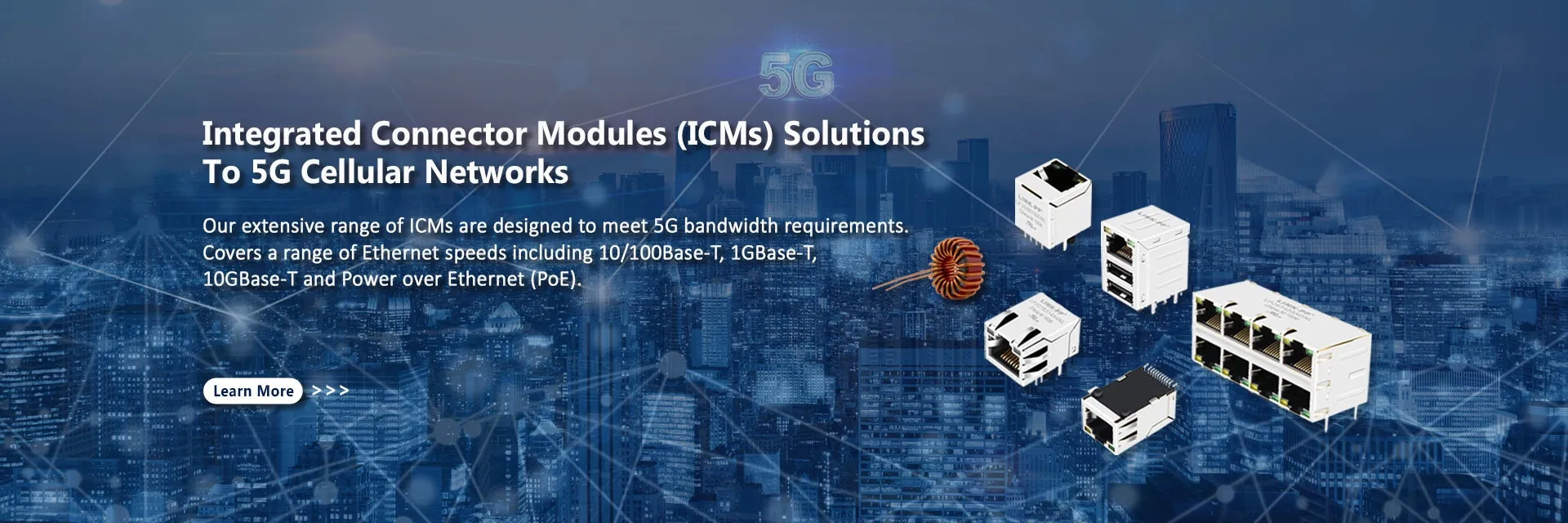
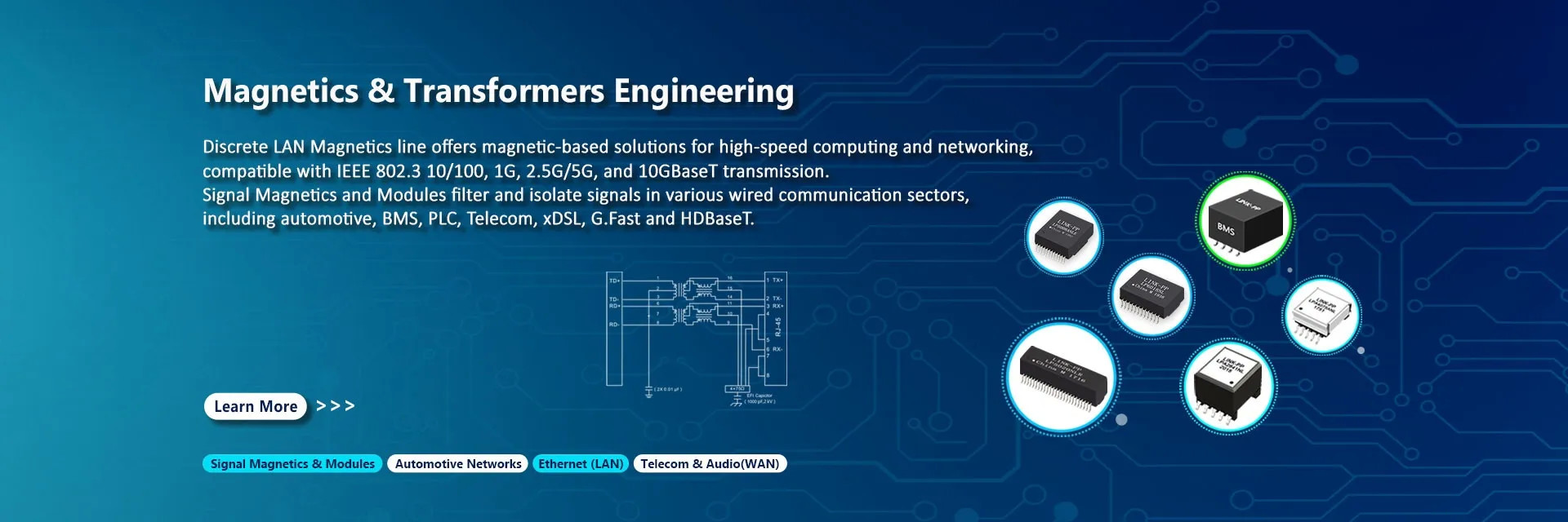
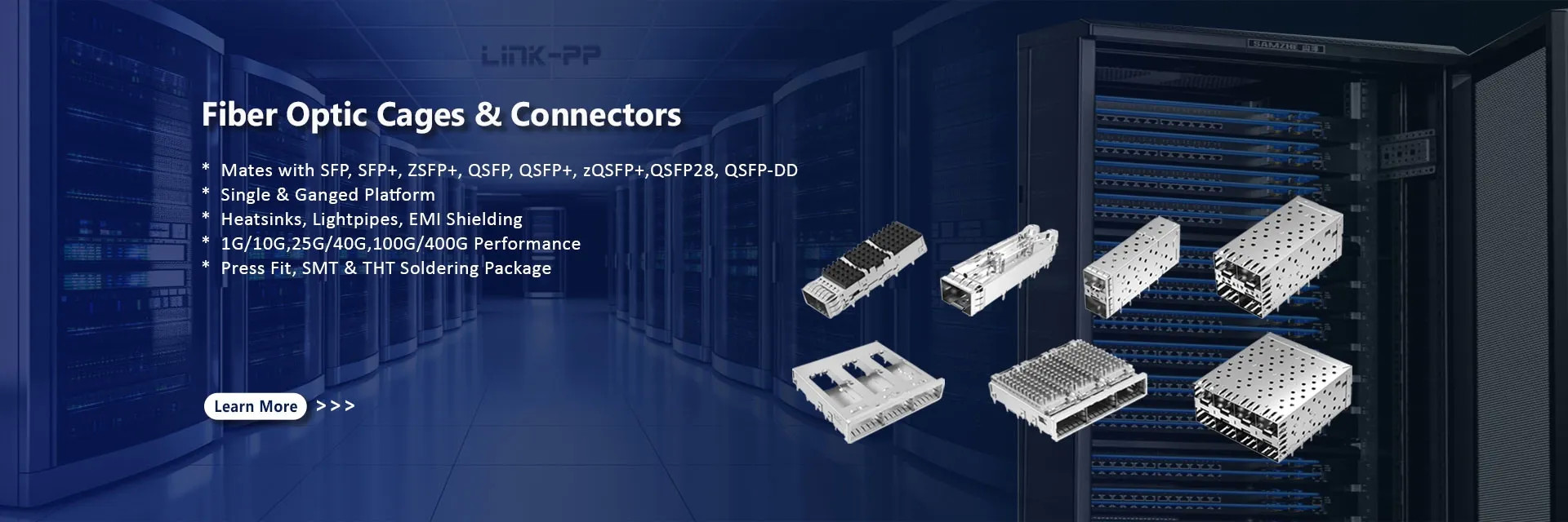
Ethernet has become the backbone of modern networking—from industrial equipment and switches to PoE cameras and embedded systems. At the heart of every reliable copper Ethernet interface lies a critical but often misunderstood component: Ethernet magnetics, also known as the LAN transformer.
This article gives engineers, hardware designers, and technical buyers a complete, authoritative reference: definitions, how magnetics work, types, PCB layout best practices, common problems from real Reddit and engineer forums, selection guidance, and future trends.
★ What Are Ethernet Magnetics?
Ethernet magnetics are magnetic transformer modules placed between the Ethernet PHY (physical layer transceiver) and the RJ45 connector to serve three essential electrical roles:
Galvanic isolation between the board’s logic domain and external cable
Differential impedance matching to the 100Ω twisted‑pair Ethernet cable
Common-mode noise suppression for EMC/EMI compliance
These magnetics are required by IEEE 802.3 standards for 10/100/1000 and Multi‑Gig Ethernet to ensure safety and signal integrity.
In simple terms, they are pulse transformers with center‑tapped windings that carry the differential Ethernet signal while isolating DC and unwanted noise.
★ Why Ethernet Interfaces Require Magnetics
Ethernet magnetics are non‑optional in standard designs for several technical reasons:
1. Galvanic Isolation
Ethernet networks connect devices across multiple ground domains. Magnetics provide 1500 Vrms or more isolation between PHY circuits and external cables to protect devices and meet safety regulations.
2. Common‑Mode Noise Suppression
Magnetics often include common‑mode chokes, which filter unwanted electrical noise that can otherwise corrupt high‑speed differential signals.
3. Impedance Matching
Ethernet twisted‑pair cables expect a 100Ω differential impedance. Transformers help match the PHY output to this value, minimizing reflections and signal loss.
★ How Ethernet Magnetics Work
A typical Ethernet magnetics module features:
TX and RX transformers with balanced center‑tapped windings
Common‑mode chokes for noise rejection
Often paired with Bob Smith termination networks for enhanced EMC
The magnetics permit differential signals to couple between PHY and cable via magnetic induction while blocking DC and suppressing common‑mode currents.
★ Types of Ethernet Magnetics
1. Discrete LAN Transformer Modules
Standalone transformer components that must be placed on the PCB between the PHY and RJ45. These give maximum flexibility in layout but require careful design.
2. Integrated RJ45 with Magnetics (“MagJack”)
An RJ45 connector with built‑in magnetics and often LED indicators. This saves PCB space, simplifies layout, and improves assembly repeatability.
3. PoE‑Ready Magnetics
Specifically designed for Power over Ethernet (PoE/PoE+/PoE++) applications with higher current handling and modified transformer structures for power injection.
★ Real Engineering LAN Magnetics Problems
Here are actual issues engineers face and how magnetics play a role:
● Ethernet Works Only at 10 Mbps
On Reddit, one engineer designing a custom board reported Ethernet working only at 10 Mbit/s, not 100 Mbit or 1 Gbit, even with proper differential impedance. Community responses pointed to PCB layout or PHY configuration issues around the LAN transformer region, suggesting magnetics placement and return path strategy matter greatly.
This is a typical issue when high‑frequency signal integrity is disrupted by misplacement, incorrect center‑tap routing, or interference at the magnetics.
● Misunderstanding Magnetics Role
Another thread explained that people sometimes mistake magnetics for just “noise filters,” but engineers emphasize they are required for isolation, safety, and standardized Ethernet operation.
● Magnetics Orientation Matters
An electronics forum discussed how orientation of magnetics matters, especially for common‑mode choke placement relative to PHY or Ethernet connector—affecting signal quality and EMC performance.
● Questions About Magnetics Omission
Some designers ask whether magnetics are needed when two Ethernet PHYs are on the same PCB. Responses indicate you can sometimes get away without them on short hops, but often magnetics or DC blocking is added to ensure robust operation, particularly with different PHY chips.
★ PCB Layout Best Practices for Ethernet Magnetics
Proper layout is critical to future‑proof designs:
Place magnetics as close to the RJ45 connector as possible
Maintain 100Ω differential trace pairs between PHY and magnetics, and between magnetics and RJ45
Avoid ground planes directly under transformers to reduce parasitic coupling
Connect center‑taps to chassis or bias networks as recommended by PHY docs
A hardware checklist from a major PHY manufacturer confirms that 1:1 isolation transformers are required and details inductance, insertion loss, and HIPOT specifications that designers must meet.
★ How to Select Ethernet Magnetics
Engineers should consider:
1. Speed Support
Fast Ethernet (10/100), Gigabit (1000BASE‑T), and Multi‑Gig (2.5G/5G/10GBASE‑T) all place different demands on magnetics performance. Discrete and integrated options exist for each speed.
2. Isolation & Safety Ratings
Look for minimum 1500 V RMS HIPOT for consumer and higher reinforced insulation for industrial or medical applications. Some high‑end transformers offer elevated isolation (e.g., 4680 V DC).
3. PoE Compatibility
Ensure PoE/PoE+/PoE++ support if power is delivered over the cable.
4. Package Type
Discrete modules vs. integrated MagJacks affect PCB area and assembly complexity.
★ Ethernet Magnetics vs Integrated MagJack
Feature
Discrete Magnetics
Integrated MagJack
PCB area
Larger
Smaller
Placement control
High
Limited
Assembly simplicity
Lower
Higher
EMI / performance tuning
Better
Good
★ Common Magnetics Troubleshooting
Link down / negotiation failure: Check magnetics placement and center‑tap connections
Speed stuck at 10/100 only: Verify impedance continuity and PHY config
EMI compliance failures: Inspect common‑mode choke placement and grounding
PoE power issues: Review magnetics current rating and transformer design
★ LAN Magnetics Future Trends
Looking ahead:
Higher speed magnetics for multi‑gig Ethernet as 2.5G/5G/10G become standard
PoE++‑ready magnetics supporting high‑power IoT and industrial feeds
More integrated components that combine transformer, choke, filtering, and connector
★ Frequently Asked Questions about LAN Transformers
Q1: What is a LAN transformer in Ethernet?
A LAN transformer, also called Ethernet magnetics, is a magnetic isolation component placed between the Ethernet PHY and the RJ45 connector. It provides galvanic isolation, impedance matching for 100 Ω differential pairs, and suppression of common-mode noise to ensure stable Ethernet communication.
Q2: Why do Ethernet ports require LAN transformers?
Ethernet standards require LAN transformers to provide electrical isolation and signal integrity. They protect internal circuits from voltage differences between devices, reduce electromagnetic interference (EMI), and help match the impedance of twisted-pair Ethernet cables.
Q3: Can Ethernet work without a LAN transformer?
In standard Ethernet interfaces, a LAN transformer is typically required to meet IEEE 802.3 isolation and EMC requirements. Some short internal connections between PHY chips may work without magnetics, but production Ethernet ports normally include transformers for safety and reliable operation.
Q4: What is the typical isolation voltage of Ethernet magnetics?
Most Ethernet LAN transformers provide 1500 Vrms isolation voltage between the cable and the internal circuitry. Higher-isolation versions may support 2250 Vrms or more for industrial or medical equipment.
Q5: What is the difference between Ethernet magnetics and an RJ45 MagJack?
Ethernet magnetics are the transformer and filtering components used in the Ethernet interface.A MagJack is an RJ45 connector that already integrates these magnetics inside the connector housing, simplifying PCB design and saving board space.
Q6: How do you select the right LAN transformer?
When selecting a LAN transformer, engineers typically consider:
Supported Ethernet speed (10/100/1000BASE-T or higher)
Isolation voltage rating
PoE compatibility
Port density (single-port or multi-port)
Package type (discrete magnetics or integrated MagJack)
Q7: What problems can occur if Ethernet magnetics are incorrectly designed?
Improper magnetics selection or PCB layout may cause:
Ethernet link instability
Speed negotiation failures (e.g., stuck at 10 Mbps)
Increased EMI emissions
Poor signal integrity
Correct placement and impedance-controlled routing are essential for reliable Ethernet performance.
★ Conclusion
Ethernet magnetics are a small but indispensable part of every reliable Ethernet interface. They provide safety, signal integrity, noise suppression, and compliance with networking standards. Whether you are designing a consumer router, industrial controller, or PoE‑enabled device, understanding magnetics intimately will set your designs apart from common pitfalls.
For engineers and technical buyers looking for industrial‑grade magnetics, consider high‑reliability discrete modules and integrated MagJack solutions that meet both performance and regulatory requirements.